Strain gauge connections and bridge circuits
How to wire a strain gauge depends on the type of instrument. See the table below for combinations of measurement method and bridge circuit.
| Measuring mode example | Bridge circuit | Wiring connection to Switching Box | Wiring connection to Bridge Box | Bridge Output |
|---|---|---|---|---|
|
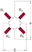
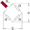
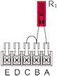
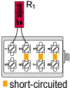
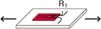
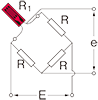
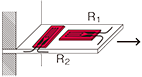
Quarter bridge
|
|
|
|
E : Input voltage e : Output voltage ⊿e : Output voltage due to strain e0 : Output voltage before strain occurrence R0 : Resistance before strain occurrence ⊿R : Resistance change due to strain ε : Strain amount K : Gauge Factor of strain gauge e = e0+⊿e R1 = R0+⊿R R = R0
|
|
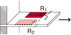
Quarter bridge 3-wire
|
|
|
|
|
|
Quarter bridge 3-wire width two gauges connected in series in one arm, eliminating bending strain |
 |
 |
 |
R1 = R0+⊿R
|
|
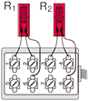
Quarter bridge width four gauges connected in series and paralleled in one arm
|
 |
 |
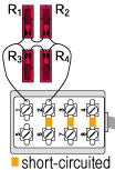 |
R1 = R2 = R3 = R4 = R0+⊿R
|
|
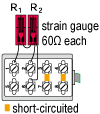
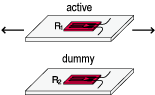
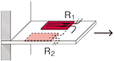
Half bridge width 1-active and 1-dummy gauge
|
 |
 |
 |
R1 = R0+⊿R
|
|
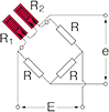
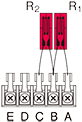
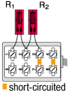
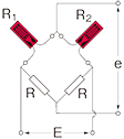
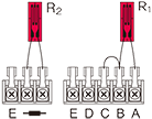
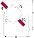
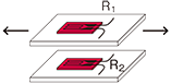
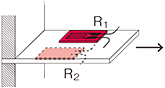
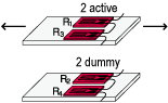
Half bridge width two active gauges
|
R1 =R0+⊿R R2 =R0-ν⊿R  ν : Poisson's ratio |
|||
|
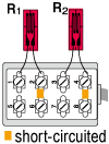
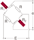
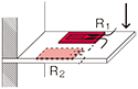
Half bridge width 2 active gauges : Bending strain
|
R1 = R0+⊿R
|
|||
|
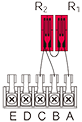
Half bridge common dummy
|
 |
 |
Only for switching box |
R1 = R0+⊿R
|
|
Opposite arm Half bridge with 2 active gauges
|
 |
Only for bridge box Accommodated models SB-120B SB-128A SB-123A |
 |
R1 = R0+⊿R
|
|
Opposite arm Half bridge with 3-wire 2 active gauges
|
 |
Only for bridge box Accommodated models SB-120B SB-128A SB-123A |
 |
R1 = R0+⊿R
|
|
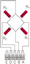
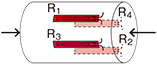
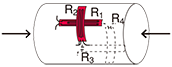
Full bridge width 4 active gauges : Uniaxial strain
|
 |
 |
 |
R1 = R3=R0+⊿R R2 = R4=R0-v・⊿R  ν : Poisson's ratio |
|
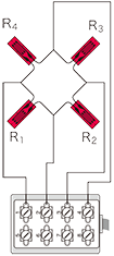
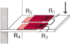
Full bridge width 4 active gauges : Bending strain
|
R1 = R3=R0+⊿R R2 = R4=R0ー⊿R ⊿e = EKε |
|||
|
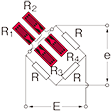
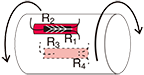
Full bridge width 4 active gauges : Torque
|
R1 = R3=R0+⊿R R2 = R4=R0ー⊿R ⊿e = EKε |
|||
|
Full bridge width 2 active and 2 dummy gauges
|
R1 = R3=R0+⊿R
|


Output voltage due to strain is based on the condition that output voltage before strain generation(e0) is zero.
More Information