Flat Compression Load Cell CLF-NA 3MN~10MN
Compression Load Cell CLF-NA 3MN to 10MN
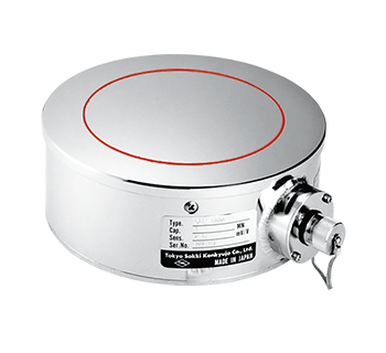
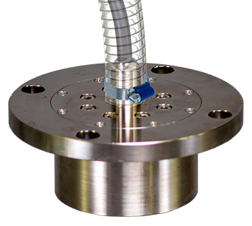
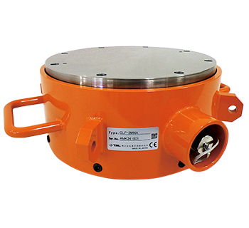
The CLF-NA Load Cell is a thin load cell with a flat load bearing surface. It is widely used as a load sensor for industrial machinery, especially when measuring loads on rolling machines or measuring compression force on presses.
Protection ratings : IP 65 equivalent
- Features
- Can be used in tight spaces in thin
- Excellent stability
- Rolling machine, press machine suitable
-
Specifications
Type Capacity Rated output Non-linearity Temperature range CLF-3MNA 3MN 1.5mV/V
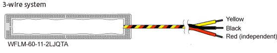
(3000×10-6 strain)±0.5%0.3%RO -20 to +70℃ CLF-5MNA 5MN CLF-10MNA 10MN Output polarity
Measurement moves in the minus direction with regard to increased compressing force.
More Information