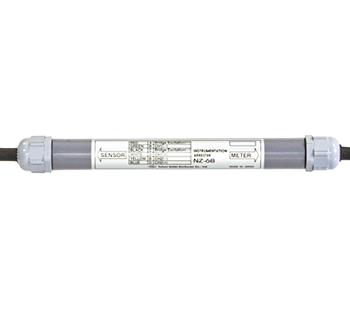
Arrester NZ-6B
Arrester NZ-6B
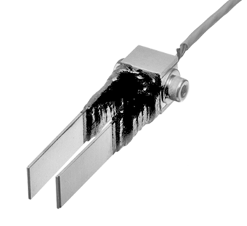
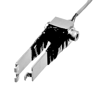
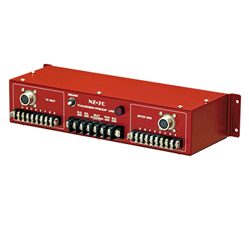
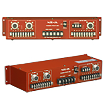
An arrester protects measuring instruments and transducers from induced lighting. In lighting-prone areas, the induced voltage of lighting traveling through the cables of measuring instruments or switch boxes can damage instruments and transducers. When placing measuring instruments and transducers, connection of NZR-7B/NZ-7C on cabling between an instrument and a switch box or NZ-6B on cabling between a transducer and switch box will protect the instrument and transducer by allowing induced current to pass to the ground.
- Features
- Large discharge capacity
- Equalized discharge circuit
- Fully waterproof
- Applicable to KM transducers with relative temperature measurement function
- Accommodates input common 2-point sensor (2-axis inclinometer)
-
Specification
Type NZ-6B Applicable sensor Strain gauge
Quarter Bridge 3-wire,
Half Bridge,
Full Bridge (including transducer)
Full bridge + Quarter Bridge 3-wire (transducer with rerative temperature measurement function)
Full bridge + Thermocouple
2-axial transducer having common input (2-axial inclinometer)Surge current resistance 10kA (8/20µs) Dimensions ø24mm, Length 225mm Weight 230g