Ultracompact Compression Load Cell
CLS-NA/CLS-NB Compression Load Cell 2N to 10kN
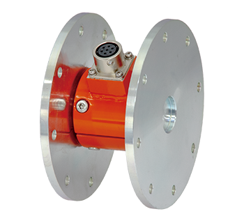
The CLS-NA and CLS-NB Load Cells are ultracompact load cells with capacities ranging from 2N to 10kN. They are widely used for measuring load distribution or loads in structural mock-up testing and as a sensor for industrial machinery.
CE marking. : CLS-NB
Protection ratings
: IP 53 equivalent / IP 41 equivalent(CLS-2NA , CLS-5NA)

- Features
- Smallest ø12 mm, lightest 1 g
- Miniature, High accuracy, High sensitivity
- Easy handling
- Ideal sensor for model testing
-
Specifications
Type Capacity Rated output Non-linearity Temperature
rangeCLS-2NA 2N 1mV/V
(2000x10-6 strain)±30%1%RO -10 to +60℃ CLS-5NA 5N CLS-10NA 10N 1mV/V
(2000x10-6 strain)±20%0.5%RO CLS-20NA 20N CLS-50NA 50N CLS-100NA 100N CLS-200NB 200N 1.5mV/V
(3000x10-6 strain)±10%CLS-500NB 500N CLS-1KNB 1kN CLS-2KNB 2kN CLS-5KNB 5kN CLS-10KNB 10kN Output polarity
Measurement moves in the minus direction with regard to increased compressing force.
More Information
High and low temperature strain gauge
CEF series High and low temperature strain gauge
CEF series high and low temperature strain gauges utilize polyimide resin for the backing and a special alloy for the element. They feature a wide range of operating temperature from −269 to +200°C.

Applicable specimen | Metal, Ceramics |
---|---|
Operational temperature(℃) | -269 to +200℃ |
Temperature compensation range(℃) | -196 to +80℃ |
Applicable adhesive | C-1, EA-2A, CN |
Backing | Polyimide |
Element | Special alloy foil |
Strain limit | 1% (10000 x 10-6 strain) |
Fatigue life at room temperature | 1 x 10⁶ (±1500 x 10-6 strain) |
-
High and low temperature Use
Gauge pattern Type Gauge
length
(mm)Gauge
width
(mm)Backing
length
(mm)Backing
width
(mm)Resistance
(Ω)Single element
(G.F. 2.1 approx.)
CEF-1-11CEFLA-1-11
CEFLA-1-17
CEFLA-1-231 0.5 4 2.2 120 CEFLA-3-11
CEFLA-3-17
CEFLA-3-233 0.6 6.9 2.8 120 CEFLA-6-11
CEFLA-6-17
CEFLA-6-236 1.0 10.6 3.1 120 Each package contains 10 gauges.
-
Leadwire-integrated CEF series (made-to-order)
Purpose Lead wires Lead wire symbol Operating temperature range(℃) Gauge type exampled High and low temperature 3-strand twisted FEP wire 6FA♦LT -269 to+200 CEFLA-1-11-6FA3LT-F 3-strand twisted FEP single-core wire 6FB♦LT CEFLA-1-11-6FB3LT-F 3-strand twisted PTFE wire 4FA♦LT -269 to+260 CEFLA-1-11-4FA3LT-F 3-strand twisted PTFE single-core wire 4FB♦LT CEFLA-1-11-4FB3LT-F * "♦" indicates lead wire length
More Information
Pi-shape Displacement Transducer
PI Pi-shape Displacement Transducer ±2mm to ±5mm
The PI displacement transducer has a simple structure; which considered an arch-shaped spring plate with strain gauges mounted on it.. Six models designed for gauge lengths of 50 mm to 300 mm are available. This transducer is used to measure the crack opening displacement occurring within each gauge length on the surface of concrete or to measure the displacement of various structures.

- Features
- Simple shape
- Stable measurement possible
- Versatile gauge lengths
- Easy handling
-
Specifications
Type Gauge Length
(mm)Capacity Rated output Sensitivity
(x 10-6 strain/mm)Non-linearity Temperature range PI-2 50,100,
150,200,
250,300±2mm Approx. 2mV/V
(4000 x 10-6 strain)Approx. 2000 0.5%RO 0 to +40℃ PI-5 ±5mm Approx. 2.5mV/V
(5000 x 10-6 strain)Approx. 1000 Output polarity
Measurement moves in the plus direction with regard to an increase of the opening.
More Information
Ring type Displacement Transducer
Bolt Strain Gauge
Bolt strain gauge series BTM/BTMC
These gauges are used for measurement of tensile strain of bolt. They are simply inserted into pre-drilled hole in the bolt with exclusive adhesives. This method is recommendable when an ordinary strain gauges can not be mounted on the bolt surface. Accurate tensile force measurement is possible by calibrating the bolt after installing the bolt gauges.

Applicable specimen | Bolt M10 or larger |
---|---|
Operational temperature | -10 to +80℃ |
Temperature compensation range | - |
Applicable adhesive | A-2 |
Backing | Special plastics |
Element | Cu-Ni |
Strain limit | - |
Fatigue life at room temperature | - |
-
Single-element
Gauge lead: polyurethane wire ø0.14, 80 mm
* The cover on the polyurethane wire can be peeled away with a soldering iron, allowing it to be worked later.Type Gauge length (mm) Gauge width (mm) Backing length (mm) Backing width (mm) Resistance (Ω) BTM-1C
(Φ1.6mm)1 0.7 5.6 1.4 120 BTM-6C
(Φ2mm)6 1.0 12.0 1.7 BTM-6CTA
Temperature-integrated(-10 to +80℃)
(Φ2mm)6 1.0 12.0 1.7 Each package contains 10 gauges.
-
We can embed a BTM (bolt strain gauge) into any bolt.
The way of adhering a BTM (bolt strain gauge) differs from a general strain gauge, requiring drilling of the bolt, embedding the strain gauge, and load calibration.
Ex.) Load calibration specifics (bolt size: M10 × 1.25, L = 65)
Load
(kN)0.0 4.6 9.2 13.8 18.4 23.0 Nonlinearity
(%RO)Calibration coefficient
(kN/1×10-6)Indicated strain
(×10-6)0 378 747 1129 1518 1916 1.1 0.0120 [We also embed temperature-integrated BTM (bolt gauge). Contact us for details.]
-
series BTMC
Single-element (G.F. 2.1 approx.)
Type Gauge
length
(mm)Gauge
center
a (mm)Backing
diameter
b (mm)Resistance
(Ω)Applicable
hole diameter
(mm)BTMC-05-D10-003LE 0.5 5 Φ0.9 120 Φ1.0 BTMC-1-D16-003LE 1 5 Φ1.5 120 Φ1.6 BTMC-3-D20-003LE 3 10 Φ1.9 120 Φ2.0 Each package contains 10 gauges.
More Information
High and low temperature strain gauge
Ring type Displacement Transducer
OU Ring type Displacement Transducer 10mm to 30mm
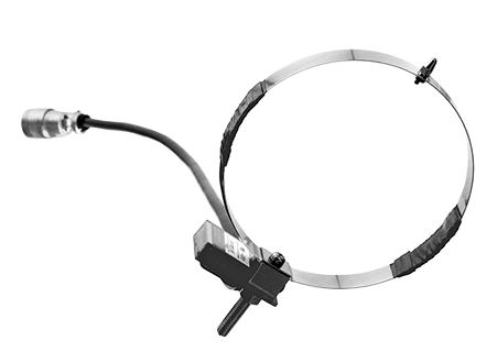
The OU displacement transducer is a combination of a round plate spring and strain gauges. It is mounted with its contact tip pressed against a structure. When displacement occurs in the structure, the plate spring is deformed and an output proportional to the displacement can be output.
- Features
- High Response
- Stable measurement with simple shape
- Easy handling
-
Specifications
Type Capacity Rated output Sensitivity
(x 10-6 strain/mm)Non-linearity Temperature range OU-10 10mm Approx. 5mV/V
(10000 x 10-6 strain)Approx. 1000 1%RO 0 to +40℃ OU-20 20mm Approx. 500 OU-30 30mm approx. 300 Output polarity
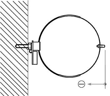
Measurement moves in the minus direction when the contact tip is pushed inward.
More Information