Track inspection data recorder
Track inspection data recorder
This is a data recorder for measuring train track conditions. Track deviation data collected by each sensor is digitized and recorded on a memory card along with location information. The recorded data is processed on a personal computer, allowing for the creation of many data analysis and documentation materials, such as track maintenance data, with little effort.
- Features
- Capable of recording 500 km of continuous measurement data (standard)
- Capable of measuring at high speeds (140 km/h)*
- Motion measurement is possible at the same time as track surveying
- Support for inputting various types of location information
- Compatible with rail seam detector
*Depends on conditions such as the number of input points, measurement distance interval, etc. Please contact us for details.
-
Specification
Analog input Max. 15 points
Orbital deviation, upset, wavy wear
Reaction plateDigital Inputs 10 points (seam, reflector, ATS) A/D converter 16-bit
Simultaneous sample hold at all pointsDisplay 6.4-inch color LCD with backlight Setting details Starting kilometer, by line name and line -
Analytics Software
Master file creation and correction
Structure, distance correction
Data analysis
P value control table, orbit deviation list, and target value exceedance location table
Create backup
*Please contact us for more information on analysis software.
System block diagram
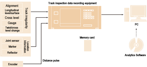
Track inspection data recorder
Hydraulic jack control unit
Hydraulic jack control unit
Hydraulic jack control unit
This device is used for load/displacement control and holding control of hydraulic jacks, and can control 2 or 4 systems. The amplifier can be controlled by a personal computer for auto-zero, range setting, calibration, etc. The detected load and displacement can be calculated by the PC as a sum of two points, averaged, etc., to control the load and displacement of the jack as desired.
Product Configuration
-
Sensor
-
Control unit
-
Electric pump unit
- Features
- 2 or 4 hydraulic jack systems can be controlled
- Amplifier can be mounted up to 12 channels
- PC control of auto-zero, range setting, calibration, etc. possible
- Detected load and displacement can be calculated by summing two points, averaging, etc.
- Load and displacement control of jacks can be automatic or manual
- Electric pump and control solenoid valve integrated
- Manual push/pull control is possible
-
Specification
Sensor Force transducer, displacement transducer Amplifier unit Number of
measurement points2 or 4 points (up to 12 points possible) Applicable
Transducers350Ω strain gage applied transducers A/D converter Resolution 12 bits PC Please contact us Displays Please contact us Actuator Number of jack
control points2 or 4 points Emergency stop possible Manual pressurization/
decompression controlpossible Control software Initial settings Amplifier sensitivity setting, rated capacity, used capacity, rated output Control Mode Target display of load and displacement, holding control Others Numerical display, status display, graph control, arithmetic processing Operating temperature and humidity range 0 to +40°C, 95% RH or less (excluding condensation) Power source Rated voltage AC100V 50/60Hz Allowable voltage AC90 to 110V 50/60Hz External dimensions 700 (W) x 1346 (H) x 700 (D) mm (excluding projections) Weight Approx. 100 kg Operation relay unit Control system 2 or 4 systems Control method Isolated photocoupler
Solenoid valve ON/OFF by time controlControl solenoid valve Control system 2 or 4 systems Hydraulic pressure 49MPa(500kgf/cm2) Flow rate control Aperture valve, push/pull 2 systems Power source AC180 to 220V 50/60Hz Electric pump Discharge pressure,
flow rate49MPa (500kgf/cm2) 0.3L/min
4.9MPa (50kgf/cm2) 5.6L/minCooler Water-cooled (optional) Effective oil storage capacity approx. 45 L External dimensions 1000 (W) x 1400 (H) x 950 (D) mm (excluding projections) Weight Approx. 650kg
System block diagram
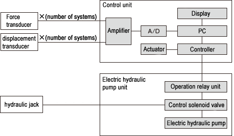
Hydraulic jack control unit
PC Steel Wire Automatic Tension Measuring Device
PC Steel Wire Automatic Tension Measuring Device
This device measures the amount of elongation and tension force during PC steel wire tensioning, automatically controls the hydraulic pump, and automatically creates a PC steel wire tension record table. Hydraulic pump control can also be operated manually.
- Features
- Automatic calculation of design tension and final elongation based on steel used, number of pieces, and effective length
- Correction calculations for maximum temperature during curing, outside temperature, etc. are also possible
- Calculations can include friction coefficients for bending up, etc.
- JIS A5373-2004 compliant
-
Specification
Displacement Transducer DP type Pressure gauge sensor PWH-PA/PW-PA type Digital Display On-site Load Indicator Recording device TML-NET type PIO Board PIO-32/32L
Made by CONTECOS DOS/V
System block diagram
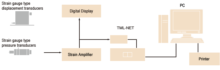
PC Steel Wire Automatic Tension Measuring Device
Wireless compact FWD system
FWD-Light® Wireless Compact FWD System Specifications/Product Configuration
Wireless Compact FWD Main Unit KFDT-100A

Wireless Compact FWD Main Unit KFDT-100A
KFD-100A is a small body falling from a heavy weight and loading of the accelerometer and built-FWD load meter free-fall will be the weight of the body weight, total amount of load and displacement values when the impact load, using an accelerometer measures. Displacement of the accelerometer measurements are derived by integrating two times.
Degree of protection IP 42 equivalent
Specifications
| Dimensions of loading plate | φ100 x 15(thick)mm |
|---|---|
| Mass of weight | 5kg |
| Falling height | 50 to 530mm |
| Falling method of weight | Lever (with stopper) |
| Maximum load | 20kN |
| Miaximum displacement | 2.500mm |
| Strain gauge based sensor | |
| Load Cell | 1 point, 20kN |
| Acceleration transducer | 1 point, 500m/s2 |
| Data acquisition | |
| Measurement range |
Range 1000:±3,000×10-6 strain |
| Resolution | 16bit |
| Communication section | |
| Transmission method | 2.4GHz band IEEE802.15.4 protocol compliant |
| Communication range | Approx. 50m at sight line |
| Number of external displacement sensors connected |
Max. 4 units |
| Power source | AA dry cell batteries (4 pcs.) Continuous use time: approx. 20 hours (at 23±5℃: with alkaline batteries) |
| Environment | -20 to +60°C, less than 85%RH (no condensation) |
| Height | Approx. 1250mm |
| Weight | Approx. 15kg. (including 5kg weight) |
Wireless external displacement sensor KFDST-1A

FWD-Light for the External Displacement Sensors up to 4 expansion units can be connected.
Degree of protection IP 42 equivalent
Specifications
| Maximum displacement |
0 to 1.000 mm (sensor is accelerometer) |
|---|---|
| External dimensions | φ90×175(H)mm (excluding protruding parts) |
| Power source | AA dry cell batteries (4 pcs.) Power source Continuous use time: approx. 20 hours (at 23±5℃: with alkaline batteries) |
| Environment | -20 to +60°C, less than 85%RH (no condensation) |
| Weight | Approx. 3.7kg |
| Communication section | |
| Communication method | 2.4GHz band, IEEE802.15.4 protocol compliant |
| Communication distance | Approx. 50m in line of sight |
Wireless FWD Controller ZT-120F/ZT-121F

The wireless FWD controller ZT-120F/-121F receives data transmitted from the main unit of the compact FWD and uses the included measurement processing software ZT-7100 to capture waveforms, monitor measurements, and capture peak force and displacement values.
The wireless controller operates on USB bus power of the connected PC.
The user can select either the ZT-120F with USB cable or the ZT-121F with built-in antenna at the time of purchase.
Specifications
| Type | ZT-120F |
|---|---|
| Communication section | |
| Communication method | 2.4GHz band IEEE802.15.4 protocol compliant |
| Communication distance | Approx. 50 m in line of sight |
| External interface | USB 2.0 compliant (cable length: approx. 1.7 m) |
| Number of connected sensors | 1 main unit, up to 4 external displacement sensors |
| Power supply | 4.7V-5.3V DC (supplied from PC via USB) 70mA MAX(DC5.0V) |
| Environment | 0 to +50℃, less than 85%RH (no condensation) |
| External dimensions | 30(W)×25(H)×65(D)mm (excluding projections) |
| Weight | Approx. 130g (including antenna and cable) |
| Type | ZT-121F |
|---|---|
| Communication section | |
| Communication method | 2.4GHz band IEEE802.15.4 protocol compliant |
| Communication distance | Approx. 50 m in line of sight |
| External interface | USB 2.0 compliant (push-in connector) |
| Number of connected sensors | 1 main unit, up to 4 external displacement sensors |
| Power supply | 4.7V-5.3V DC (supplied from PC via USB) 100mA MAX(DC5.0V) |
| Environment | 0 to +50℃, less than 85%RH (no condensation) |
| External dimensions | 35(W)× 11(H)× 65(D)mm (excluding projections) |
| Weight | Approx. 30g |
Measurement Processing and Software ZT-7100

Measurement processing software ZT-7100 is used for waveform acquisition, measurement monitoring, and acquisition of peak force and displacement values.
Specifications
| Function | |
|---|---|
| Measuring function | Measurement function waveform acquisition, measurement monitoring, and load/displacement peak value acquisition |
| Setting Functions | Test condition setting, amplifier input setting, A/D conversion setting, option setting |
| List function | Graph display, list display, correlation graph display |
| Conversion Functions | CSV file conversion |
| Operating Environment | |
| OS | Windows 7/8.1/10 |
| CPU | Pentium150MHz or higher recommended |
| Memory | 128M bytes or more recommended |
| Hard disk | 2 GB or more |
| Display | 1024 x 768 dots or higher resolution |
| Interface | USB 2.0 compliant, recognized as virtual COM port |
| Measuring instrument | Wireless controller: 1 unit Compact FWD main unit: 1 unit Up to 4 external displacement sensors (optional) |
Options
| Product Name | Type | Product photo | Notes |
|---|---|---|---|
| External Displacement Sensor | KFDST-1A | 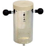 |
|
| Added weight drop(10kg) | KFDF-11-10 | 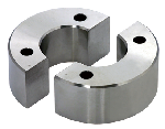 |
|
| Added weight drop(15kg) | KFDF-11-15 | ||
| Loading plate(φ90mm) | KFDF-31-90 | 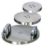 |
φ90×t15mm |
| Loading plate(φ150mm) | KFDF-31-150 | φ150×t15mm | |
| Loading plate(φ200mm) | KFDF-31-200 | φ200×t15mm | |
| Loading plate(φ300mm) | KFDF-31-300 | φ300×t22mm | |
| Rubber buffer | KFDF-51 | 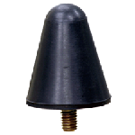 |
|
| Simple calibration device | KFDF-61 | 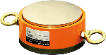 |
Simple calibration equipment for measuring data to confirm this at the scene |
| Mobile Storage Aluminum Case | KFDF-21-2 | 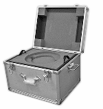 |
Weight for weight with storage options / external displacement |
| Careers | KFDF-42 | 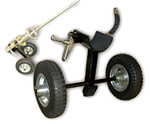 |
FWD-Light fixtures only move |
| Portable and storage aluminum case | KFDF-21-3 | 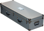 |