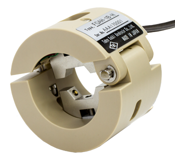
Small FWD System FWD-Light
FWD-Light® Product Configuration
Product Configuration
| Product Name | Compact set | Standard set | Notes: Standard accessories |
|---|---|---|---|
| Main Body KFD-100A Built-in sensor acceleration transducer load cell |
 |
 |
weight (5kg):KFDF-11-05 Loading plate (ø100 x 15(thick)mm) :KFDF-31-100 5m cable |
| Exclusive Indicator TC-351F Of view (21 digits × 8 lines) RS-232C interface Card slot |
 |
 |
AC Power Battery Pack |
| Mobile Storage Aluminum Carrying Case KFDF-21-1 |
- |  |
Storage: body, only indicator options (external displacement sensor, the printer only) |
| 64MB Compact flash memory card |
- |  |
|
| Memory card adapter | - |  |
Small FWD main body KFD-100A
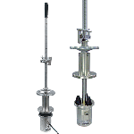
KFD-100A is a small body falling from a heavy weight and loading of the accelerometer and built-FWD load meter free-fall will be the weight of the body weight, total amount of load and displacement values when the impact load, using an accelerometer measures. Displacement of the accelerometer measurements are derived by integrating two times.
Degree of protection IP 42 equivalent
Specifications
| Dimensions of loading plate | φ100 x 15(thick)mm |
|---|---|
| Mass of weight | 5kg |
| Falling height | 50 to 530mm |
| Falling method of weight | Lever (with stopper) |
| Maximum load | 20kN |
| Miaximum displacement | 2.500mm |
| Strain gauge based sensor | |
| Load Cell | 1 point, 20kN |
| Acceleration transducer | 1 point, 500m/s2 |
| Data acquisition | |
| No. of measuring points | 2 points (load nad acceleration) |
| Measuring accuracy | ±(0.1%rdg+2digit) (at23±5℃) |
| Data memory | 800 data/point |
| Sampling speed | 50μs |
| Trigger function | By data (load value) Trigger method Data trigger recording |
| Interface | Exclusive 2-wire serial transfer |
| No. of external displacement sensor | 4 points at maximum |
| Power source | Supplied by TC-351F |
| Environment | -20 to +60°C, less than 85%RH (no condensation) |
| Height | Approx. 1100mm |
| Weight | Approx. 15kg. (including 5kg weight) |
External Displacement Sensor KFDS-1B

FWD-Light for the External Displacement Sensors up to 4 expansion units can be connected. 5m cable included
Degree of protection IP 42 equivalent
Specifications
| Maximum displacement | 0 to 1.000mm (accelerometer sensor) |
|---|---|
| Dimensions | φ79 x 125(H)mm (excluding protrusions) |
| Mass | Approx. 1.5kg |
TC-351F only indicator
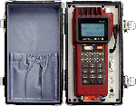
TC-351F is only a small indicator FWD measurement results via display system with LCD display to record the flash memory card indicator. Measurement data recorded in computer memory card can be read and inserted into a PC card slot. In addition, optional software measurement process can be measured in the TC-7100 using the online. Online measurements can also be incorporated into your PC as well as raw waveform data analysis.
Specifications
| Indicator | 128 x 64 dots liquid crystal display |
|---|---|
| Content View | |
| Display Monitor | Load, acceleration sensor * external acceleration, time |
| Analysis show | Maximum load value, the maximum displacement displacement displacement sensor * maximum external coefficient of subgrade reaction (KTML), soil modulus (ETML) Last-minute analysis and three times, including four minutes show times |
| View sample | |
|
|
|
| Recorded data display | Namba consecutive record data file specified in the memory card data along with records of three times |
| File Management | File management record data file specified No initialization data erase memory card recording |
| Real-time clock | |
| Settings | Year, month, day, hour, minute, second |
| Accuracy | ±2sec/day (at 23±5℃) |
| Memory Card recording analysis | |
| Standard Card | PC Card Standard compliant (TypeII) |
| Card type | Compact flash memory card (with adapter card) or ATA flash memory |
| Card capacity | 8 to 128 Mbyte |
| Recording Format | CSV file |
| Measurement processing software interface options (TC-7100) when using | |
| Standards | RS-232C |
| Features | Receiving control commands, Sent to the printer only print out the measurement data |
| Power | |
| Battery | Ni-MH battery pack |
| Hours continuous use | Approx. 32h, or approx. 1000 times measured(at 23±5℃) Standard configuration in a state of full charge (without options) at 30 times / When did the measurement of time |
| Vibration resistance | 30m/s2 (at 50Hz 0.6mmp-p) |
| Waterproof | IP-54 (installed state Connector cap) |
| Operating temperature and humidity range | -10 to +50℃ 85%RH or less (noncondensing) |
| Dimensions | Approx. 150(W) x 120(H) x 265(D)mm (excluding protrusions) |
| Mass | Approx. 3kg |
Options
| Product Name | Type | Product photo | Notes |
|---|---|---|---|
| External Displacement Sensor | KFDS-1B | 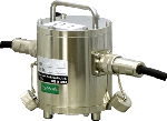 |
5m cable included |
| Added weight drop(10kg) | KFDF-11-10 | 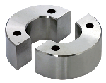 |
|
| Added weight drop(15kg) | KFDF-11-15 | ||
| Loading plate(φ150mm) | KFDF-31-150 | 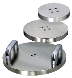 |
φ150×t15mm |
| Loading plate(φ200mm) | KFDF-31-200 | φ200×t15mm | |
| Loading plate(φ300mm) | KFDF-31-300 | φ300×t22mm | |
| Simple calibration device | KFDF-61 |  |
Simple calibration equipment for measuring data to confirm this at the scene |
| Rubber buffer | KFDF-51 | 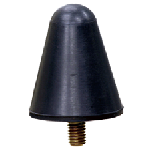 |
|
| Mobile Storage Aluminum Case | KFDF-21-2 | 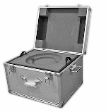 |
Weight for weight with storage options / external displacement |
| Careers | KFDF-41 | 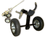 |
FWD-Light fixtures only move |
| Software measurement process | TC-7100 |  |
For Windows |
| RS-232C cable | CR-5360 |  |
|
| 128MB flash memory card capacity | Uses card adapter | ||
| Printer only | DPU-S245 | 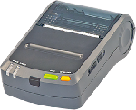 |
|
| Printer cable | CR-4530 | ||
| Printer paper | TP-S245L-1 |

 marked when using the optional external sensor
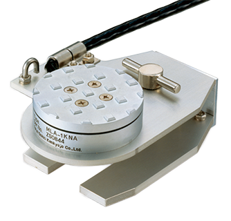
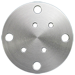 ARJF-11
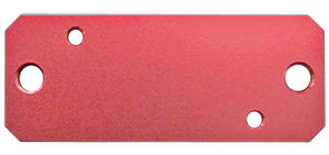 ARJF-12
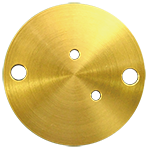 ARFF-11
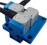 ARFF-12
 ARHF-11
 ARSF-11


