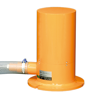
Settlement Transducer KLA-A Settlement Transducer / NKLA-B TML-NET type Settlement Transducer
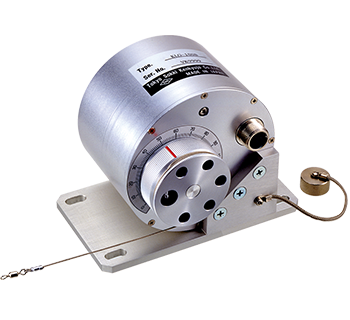
KLA-A Settlement Transducer
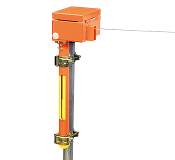
NKLA-B TML-NET type Settlement Transducer 100 mm to 200 mm
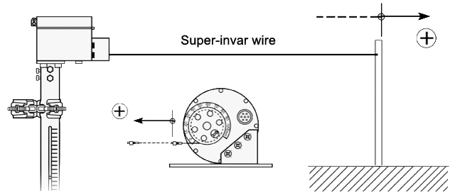
This is a settlement gauge that is set on a ground surface to measure the settlement of each ground layer. Special anchors are placed at target positions in a borehole, and the displacement between the anchors and the ground surface is measured. Measurement can be made at a maximum of six levels in one borehole.
* For information on network-capable NKLA-B, see special measurement systems.
Protection ratings : IP 45 equivalent
- Features
- Remote measurement
- Measures the amount of settlement at the maximum 6 positions.
-
Specifications
Type No. of measurement Capacity Rated output Non-linearity Temperature range KLA-100A-○ 1 to 6 100 mm Approx. 2.5 mV/V
(5000 x 10-6 strain)1 %RO -20 to +60 ℃
(no incing)KLA-200A-○ 200 mm Type No. of measurement Capacity Rated indication Non-linearity Temperature range NKLA-100B-○ 1 to 6 100 mm Approx. 5000 digit 1 %RO -20 to +60 ℃
(no incing)NKLA-200B-○ 200 mm * “◯” under “Type” corresponds to the number of measurements, 1 to 6.
Output polarity
Measurement moves in the plus direction with regard to an increase in settlement.
More Information