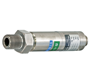
Cavity type Pressure Transducers PWH-PA
PWH-PA High capacity Pressure Transducer 70 to 200MPa
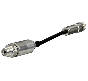
The PWH-PA high-capacity pressure transducer has a sealed structure made with high-strength stainless steel.Owing to this structure, stable high-accuracy measurement can be made over a long period of time. It is used to control plant or production lines, to measure jack pressure, and for various other applications.
Protection ratings : IP 65 equivalent
- Features
- Excellent stability, High precision
- Easy handling
-
Specifications
Type Capacity Rated output Non-linearity Temperature range PWH-70MPA 70MPa 1 mV/V (2000x10-6 strain)±1 % 0.2 %RO -20 to +70 ℃ PWH-100MPA 100MPa PWH-150MPA 150MPa PWH-200MPA 200MPa Output polarity
Measurement moves in the plus direction with regard to an increase in pressure.
More Information