Instruments FAQ
Data logger in general
-
What is the accuracy ±(0.05% rdg + 1digit) as given in the data logger specifications?
rdg → reading. (display value)
e.g. 20,000 ± 0.05%
The reading is then in a range from 19,990 to 20,010. A 1digit error is added to this range.
For strain measurements, 1digit ≒ 1 × 10⁻⁶. -
I want to use uninterruptible power supply (UPS). As long as it’s UPS, is anything okay?
Use a synchronizing-type constant inverter system.
Do not use non-synchronizing power supplies. Our data loggers use power supply frequency (50 Hz or 60 Hz) to cancel ham noise. Therefore, if a non-synchronizing power supply is used, the data may vary greatly.
TDS-530
-
Amplifier voltage output is measured in TDS-530 voltage mode. The software uses TDS-7130, but only "1" is displayed when the voltage is 1 V.
If the TDS-530 is set to Simple Measure, the decimal value and unit are displayed, as in "1.0000V". If Simple Measure is not used, the decimal digits and unit must be manually set.
Select a format such as #. #### ##. ### ###. ## . -
Can you obtain the average values of four displacement transducer CDP-50 units?
This cannot be done on the units themselves, but it is possible to do so by using a junction box JB-4.
TDS-630 provides arithmetic functions, so you can also view averages, etc. -
I set parameters such as units, but they are not reflected in the monitor.
If set to Simple Measure mode. manually entered settings will not be reflected. Cancel Simple Measure mode.
-
How do you set parameters for load cell CLH-1MN?
Since the rated power is 3000 με at a capacitance 1 MN = 1000 kN, the calibration coefficient is 1000 ÷ 3000 ≒ 0.33333.
Therefore, by setting the coefficient = 3.3333 E-1, unit = kN, and display digits = ######, entering 1000 kN causes 1000 kN to be displayed. -
How do you set parameters for displacement transducer CDP-5?
Since the rated output is 10000 με at a capacity of 5 mm, the calibration efficient is 5 ÷ 10000 = 0.0005.
Therefore, by setting the coefficient = 5.0000 E-4, unit = mm, display digits = ###.###, entering 5 mm causes 5.000 mm to be displayed. -
What is the sensor mode when a 300-kN load cell is used to connect a sensor that outputs 5 V?
Set the DC voltage to 64 V (1/100).
-
How do you set the sensor display for directly reading physical quantities?
For a sensor that outputs 5 V at 300 kN, by setting calibration coefficient is 300 ÷ 5 = 60, the coefficient = 6.00000 E+1, unit = kN, and display digits = ######, entering 300 kN causes 300 kN to be displayed and physical quantities can be read directly.
Setting display digits = #####.# displays 300.0 kN. -
I am performing measurement with a personal computer connecting by LAN. How do you export the data memory?
From My Network, open the workgroup and look for the icon “Tml”. The folders data_memo and cf_card are located there, and you can read the recorded data.
-
Four points were measured using a 2-gauge common. When a point was added later, the added point was displayed ****I****. What do you do?
This occurs because the initial value of the added point was not obtained. You can obtain the initial value for the added point alone by setting that channel only to the monitor channel, and using the “initial” function of the monitor value.
-
Even if measurement units are set, με is still displayed on the monitor.
If set to Simple Measure, manually entered settings will not be reflected.
Cancel Simple Measure mode. -
It’s set to Direct, but some channels are in “Small m” measure.
Since Comet is set, select "Not use".
-
A strain gauge is connected, but the display reads ****I****. What does that mean?
This is displayed when the initial value is not obtained or when the initial value storage range (±160000) is exceeded.
Network measuring systemTML-NET
-
Is this network type usable in a LAN or telephone network?
You cannot connect directly. Send data from a data logger via LAN or modem.
-
Can you use it in combination with a data logger?
Use the network driver ND-100 to mix with a switching box.
-
Is connection work a hassle compared with a switching box that can connect 50 points per unit?
When the measurement points are far apart, sensors for network modules can be wired in a star-type cascade connection, so wiring distance is shorter than with centralized wiring to the switchbox, making it easier to wire.
-
Can you use power-saving modules and conventional NSW-011B and NSW-014B as they are?
They can be mixed. However, the number of measured points and extension distances are by B-type specifications for NSW-011B and NSW-014B.
-
Can you install it outdoors and use it for long-term measurement? Is there a protective cover?
For outdoor use, long-term measurement is possible using a storage case so it is not exposed to rain, etc.
-
It gives “dedicated 2-conductor shielded cable”. Can other cables be used for extension?
Other multi-conductor cables are not recommended because they may affect the transmission signal.
-
Can you extend the cable between networked inclinometers?
Extension to each hole is possible by using a dedicated cable.
TC-32K
-
How long can you connect a CSW-5B to a TC-32 K and measure with 1-hour sleep intervals?
Measurement is possible up to about 2400 hours (100 days) using a battery in a normal temperature environment.
-
How long can it be used with a battery?
It can be used continuously for 10 hours. With a 1-hour sleep interval, for 116 days.
-
Even if the unit is set to kN, με is displayed on the monitor.
If set to Simple Measure, the unit setting is not reflected. Cancel Simple Measure mode.
-
I want to monitor TC-32 K measured values on a computer. Is there any such software?
You can use Visual Log Light TDS-700L.
-
I am going to measure with a connected load cell. How do you set the parameters?
Set the coefficient, display digits, and unit. The coefficient can also be set by entering the rated capacity, rated output, etc. from the Cap/RO setting by referring to the test data included with the load cell.
-
Can the 1-gauge 4-wire method be used without an adapter?
Connect wires (with no connector plug) to the input terminal to allow it to be used with the TC-32K or one of our switching boxes.
-
How can I view the data recorded on a CF card on a computer?
Insert it in a computer using a commercially available card reader to read it. The data can also be viewed on the TC-32K.
-
How does the display appear when a thermocouple is not connected after setting it to thermocouple mode?
When entry is open, by default no set values are displayed.
Select measurement setting options from the menu, then set burnout check to on in the next screen, and the display will show "********" when a thermocouple is not connected. -
The CF card is not recognized.
Check the format of the CF card. Only FAT16 is supported with TC-32K.
-
I’m recording data to data memory and CF card. What happens when the data memory is full?
If the ring buffer is set to "Off", no more data will be recorded in the data memory. If "On", old data is discarded as new data continues to be recorded.
Data continues recording on a CF card. One file can store 65000 items of data, and new files are automatically created. -
Can you measure multiple points using TC-32K?
Using the dedicated switching box CSW-5B allows five points to be measured automatically.
Up to 10 switching boxes can be managed by connecting and measuring multiple switching boxes.
DC-204R/DC-104R
-
The synchronizing cable is only 20 cm — can it be extended?
Synchronizing cables cannot be extended.
-
How many dB per octave is the decrease with the characteristics of the low-pass filter?
There is a decrease of 12 dB per octave. (-12 dB/oct)
The DC-204R/DC-104R low-pass filter is of the Butterworth type (phase-flat type). -
The start trigger does not activate. What do you do?
The data trigger does not activate if neither the level or slope match the settings.
The trigger is valid with regard to the measured strain value (or voltage value) before multiplying by the coefficient. It is not valid by setting the coefficient to -1 and reversing the polarity and the slope gradient. This will not activate the trigger.
(However, if the coefficient is set to -1, the polarity is reversed in the monitor display.)
For instance, if you want the trigger to activate at level: -20 and slope: down, merely setting the coefficient to -1 and then setting level: +20 and slope: up will not allow the trigger to activate. Set level: -20 and slope: down.
The trigger level setting is at 1% pitch intervals from 0 up to ±100% of the full scale being set.
Example: Full scale being set: 1% of 5000 με = 50 με pitchIf the setting level is too low, drift or noise may activate the trigger.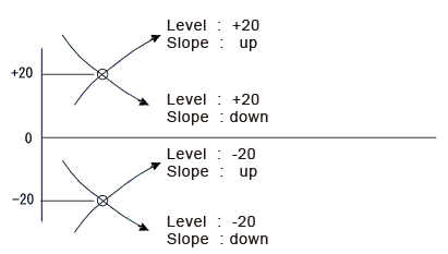
-
I'd like to use a battery to measure for a long period of time. How many batteries should I prepare?
For example, suppose a measurement period of one week.
Assuming up to 0.4 A of consumption current with the DC-204R/DC-104R
0.4 (A) × 24 (h) × 7 (days) = 67 (Ah)
A battery of about 70 Ah is required. However, considering natural discharge of the battery, temperature of the environment, and to be safe, a battery of about twice this capacity is necessary (three or four 38-Ah car batteries).
The following system would be used when measuring using a solar panel system.
It is necessary to select the model that provides sufficient solar panel and battery capacities to be safe.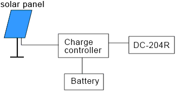
Measuring using an optional battery pack BA-104,
AA Ni-H battery: approx. 5 hours (normal temperature)
Alkaline dry batteries: measurement to about 3 hours (normal temperature).
When using batteries, do not mix new batteries with old batteries, different types, brands, etc.
If using rechargeable batteries, use batteries charged at the same time.* Consumption current of DC-204R/DC-104R
The current consumption is 3.5 VA according to the specifications. If the bridge is 350 Ω, it will be slightly smaller. Also, it will be reduced with the use of fewer CHs.
The power supply to the DC-104R is 10 to 16 VDC. -
Do you have to power on the USB hub (AC adapter) when connecting more than one DC-204R/DC-104R? Depending on the hub, there may or may not be an AC adapter. What do you do?
The USB hub does not need to be powered on (AC adapter).
DC-204R/DC-104R is not powered by a USB connection. However, power must be supplied to each DC-104R. -
In a free run with the DC-204R/DC-104R, one measurement session was recorded in more than one file. In sorting the data, the data connects where each file joins, but since the header times are in seconds, the times do not join perfectly. What do you do?
Although the header time is in seconds, samples are in μsec or msec, so times will not match exactly. Since the file size cannot be exactly divided by one second, there is a difference between the header times and the number of samples. Calculate the time by the number of samples based on the time of the first file.
-
How do you synchronize when measuring with multiple devices?
Measurement is possible with simultaneous sampling by up to eight DC-204R/DC-104R (32ch).
Synchronizing cable CR-6180 (optional) is required to synchronize measurements with multiple units.
Connect the first DC-204R/DC-104R OUT to the next DC-204R/DC-104R IN. Connect the next unit in the same way.
The unit with a free IN connector automatically becomes the master. As soon as the master starts sampling, the slave units start sampling, and end sampling at the same time. Also, be sure to set all of the following items for multiple DC-204R/DC-104R units measuring at the same time so the settings are the same. Measurement will not be possible if they are different.Items that must be set the same when multiple units are measuring
- Number of used channels
- Trigger mode
- Sampling rate
- Measured data size
- Pre-area
NOTE Turn off all DC-204R/DC-104R to connect the synchronizing cables.
Turn on the power first starting with the master.
Measurement and system relationship Measurement system
-
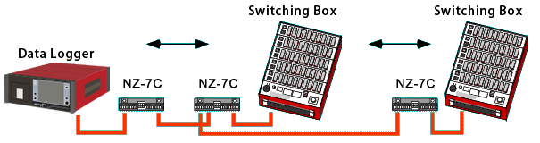
Describe how to install arresters when switching boxes are distributed in multiple locations.
It is usually necessary to install arresters at both ends of the extension cables so that the system is not affected by lightning from the outdoor switching box extension cables. If switching boxes are installed at several locations, NZ-7B arresters can be installed using the arrester connectors and terminal boards as shown in the figure below.